
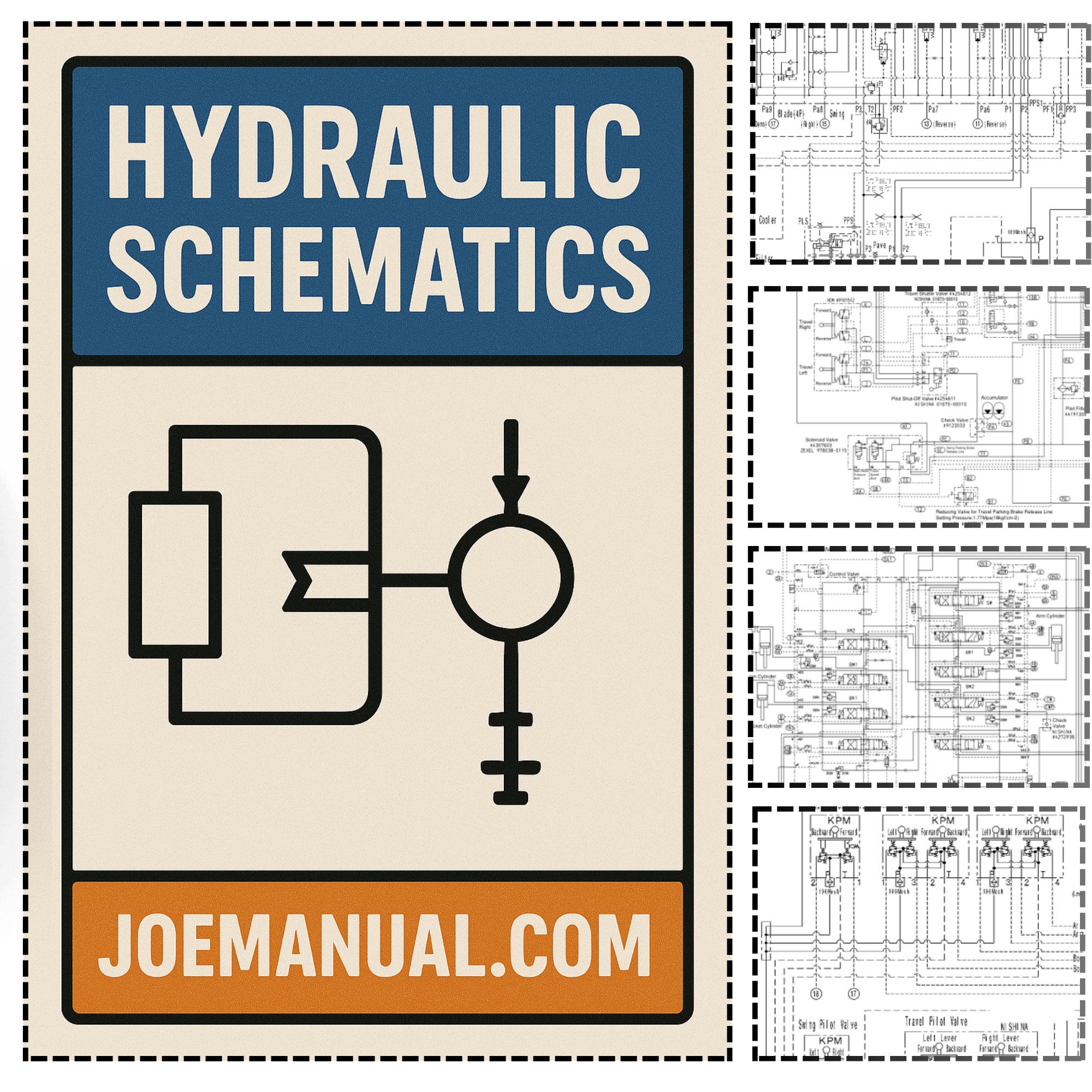
Description
Wacker Neuson 701 s Skidsteer Hydraulic Diagrams
The Wacker Neuson 701 s Skidsteer Hydraulic Diagrams provide essential technical documentation for maintaining and servicing the hydraulic systems of this compact skidsteer. Access to accurate hydraulic system layouts is critical for technicians performing component replacement, pressure testing, or fault diagnosis. Without precise reference material, incorrect hose routing or valve identification can lead to system failure and unplanned machine downtime.
This document contains hydraulic circuit diagrams and component connection layouts specific to the Wacker Neuson 701 s model. It supports professional service protocols by clarifying system architecture and flow paths, reducing the risk of improper intervention that could compromise technician safety or equipment integrity. The Wacker Neuson 701 s Skidsteer Hydraulic Diagrams are developed in line with the manufacturer’s engineering standards, reflecting the brand’s established reputation for durable and precisely built equipment. Specialized model-specific guidance is required because general hydraulic knowledge does not account for proprietary circuit design and pressurized system tolerances found in Wacker Neuson machinery.
For service personnel working on the 701 s skidsteer, this technical resource delivers the verified information needed to conduct hydraulic maintenance correctly and efficiently.

Reviews
There are no reviews yet.