

Description
Liebherr L524 Wheel Loader Work Hydraulic Diagram
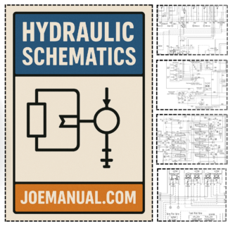
The Liebherr L524 Wheel Loader Work Hydraulic Diagram provides essential hydraulic system layouts for the L524 model, enabling technicians to accurately identify component connections and flow paths. This resource is indispensable for diagnosing pressure drop issues, verifying pump and valve positions, and planning component replacements without risking inadvertent damage to the hydraulic circuitry. By using the specific technical documentation, service personnel can follow precise procedural steps, reduce the likelihood of errors, and maintain compliance with manufacturer safety standards.
Key features of the diagram include detailed circuit schematics, component identification markers, and clear labeling of hydraulic lines and reservoirs. These elements allow for rapid reference during maintenance tasks, ensuring that each intervention is performed with full awareness of system interdependencies. The layout also supports troubleshooting of leaks, pressure inconsistencies, and valve failures, contributing to shorter repair times and fewer system resets.
Incorporating the Liebherr L524 Wheel Loader Work Hydraulic Diagram into routine service protocols safeguards both equipment life and technician safety. The precision of this specialized guidance surpasses general maintenance knowledge, reinforcing Liebherr’s reputation for engineering excellence and reliable performance.

Reviews
There are no reviews yet.