


Description
Liebherr L524 L538 Wheel Loader Hydraulic Diagram SN 0101/6870
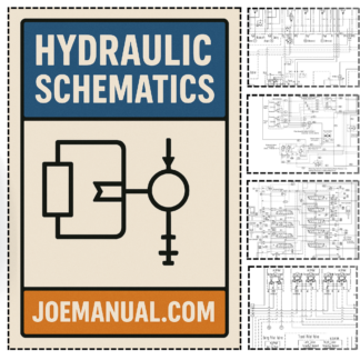
The Liebherr L524 L538 Wheel Loader Hydraulic Diagram SN 0101/6870 provides essential, precise information for maintaining the hydraulic systems of this heavy‑equipment model. By referencing the exact circuit paths and component connections, service technicians can quickly identify fault locations, streamline repairs, and reduce unplanned downtime. The diagram’s clear layout of hydraulic lines, pressure points, and valve arrangements ensures that maintenance activities are performed safely and in accordance with the manufacturer’s specifications.
Key features of the document include detailed hydraulic circuit schematics, component identification numbers, and a comprehensive overview of system interconnections. These elements allow technicians to verify part compatibility, adhere to proper pressure limits, and execute troubleshooting steps with confidence. The targeted nature of the diagram eliminates guesswork, enabling accurate diagnostics and efficient repairs that protect both the machine and the operator.
Incorporating the Liebherr L524 L538 Wheel Loader Hydraulic Diagram SN 0101/6870 into a maintenance routine is a practical step toward maximizing equipment reliability. Its focused, technical content supports adherence to professional service protocols, safeguarding operator safety while preserving the longevity of the loader’s hydraulic system.
Reviews
There are no reviews yet.